Student Projects
VM495

Testing the Cooling Performance of Compact Heat Sinks with Different Fin Intervals and Heights
Team Members: Hu Zhebang, Lin Muxing, Ma Zhihao, Yang Ruimin and Zhou Ruixing
Project Video
Team Members
Team Members:
Hu Zhebang, Lin Muxing, Ma Zhihao, Yang Ruimin and Zhou Ruixing
Instructor:
Chien-Pin Chen & Kwee-Yan Teh
Project Description
Introduction & Objectives
- Problem: Increasing high-density electronics packaging.
- Solution: compact heat sinks.
Objectives:
a) Test the cooling performance of aluminum heat sinks with different structures.
b) Derive empirical dimensionless relationships within the wind tunnel cooling configuration.
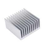
Figure 1. A typical compact heat sink
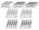
Figure 2. Heat sinks with various fin structures 1
Theoretical Backgrounds
- 𝑹𝒆=𝑼 𝑺/𝒗, S – interval of heat sink, U – wind velocity, 𝑣 – kinematic viscosity.
- 𝐍𝐮=〖𝟎.𝟑𝟑(𝑹𝒆 𝑺/𝑾)〗^(𝟎.𝟔𝟑), (2<𝑅e 𝑆/𝑊<2×〖10〗^3), 𝑊 – width of heat sink.
- 𝒉=𝝀𝑵𝒖/𝑺=𝒒/(𝑨×𝜟𝑻),
𝜆 – material thermal
conductivity,
𝑞 – input heat,
𝐴 – dissipation area,
Δ𝑇 – the difference
between heat sink and
ambient temperature.
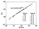
Figure 3. Performance in forced convection 2
Experimental Setup
Equipment: wind tunnel, heat sinks, IR camera.
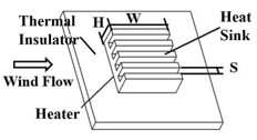
Figure 4. Major components of heat sinks
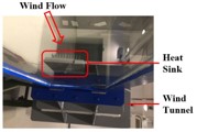
Figure 5. The forced wind setup

Table 1. Dimensions of the three heat sinks

Table 2. Wind tunnel revolutions
Experimental Results
- Forced wind cooling configuration illustrated by an IR camera.
- Wind flow comes from the left.
- Obvious air convection on the right.
Dimensionless relationship:
𝑁𝑢=7.457(𝑅𝑒×𝑆/𝑊)0.67
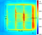
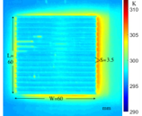
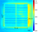
Figure 6. The temperature distribution of heat sinks in the wind tunnel
- The heat transfer coefficient increase with the increase of wind speed and sink interval.
- Dimensionless relationship:
𝑁𝑢=7.457(𝑅𝑒×𝑆/𝑊)0.67

Figure 7. Relationship between heat transfer coefficient and wind speed.

Figure 8. Relationship between Nu and Re in logarithm condition.
Conclusion
- The relation between 𝑁𝑢 and 𝑅𝑒 is found.
- The cooling performance of aluminum compact heat sinks will be improved if increasing the forced wind speed or the heat sink interval.
- The height of the heat sink may not have large impacts, but further variable-controlled experiments are necessary for proof.
Reference
1. Jonsson, Hans, and Bahram Moshfegh. “Modeling of the thermal and hydraulic performance of plate fin, strip fin, and pin fin heat sinks-influence of flow bypass.” IEEE Transactions on Components and Packaging Technologies 24.2 (2001): 142-149.
2. Ishizuka, M., Y. Yokono, and D. Biswas. “Experimental study on the performance of a compact heat sink for LSI packages.” Proceedings of the Institution of Mechanical Engineers, Part A: Journal of Power and Energy 214.5 (2000): 523-530.
